People can think of this as a small guide for those who are using P5K-V and may be VM I assume, as both are same except the later one being a micro ATX board. I will try to explain some key BIOS settings here required for a good stable overclock. Kindly note that these are the settings that worked best for my rig but that doesn’t mean that it will work best for you. You may need to change a bit here and there depending on your other hardware but hopefully it will provide you a solid base and understanding to work around with your bios. I would also suggest to read some basic overclocking guides before coming to this.
Throughout this guide I’ll be using Q6600 2.4GHz with G0 Stepping and a 9x multiplier. Keep in mind that I used THERMALRIGHT ULTRA 120 with 95CFM VANTEC 120mm fan to cool the CPU inside CM 690 casing with 6x120mm fans installed for intake and exhaust. If you are planning to do a decent overclock use a good CPU COOLER. These boards only come with 3 Phase power design rather than 6 phase or 8 phase (usually available in high end boards), which makes the Mosfets and CPU socket surroundings quite hot during overclocking.
Following softwares are used for testing and monitoring:
OCCT for stress testing
EVEREST ULTIMATE for monitoring temps and voltages
CPUZ 1.44.1 for monitoring voltages
SPEEDFAN 4.34 for monitoring temps and voltages
CORETEMP 0.98 for monitoring core temperatures (most accurate)
CRYSTAL CPUID for cross checking core temperatures.
OK, let’s start from BIOS, which in my case is 0603. The good thing about P5K-V bios is that all of the overclocking settings, including memory timings and voltages are all on the same page, so that make things quite easier.
Open the BIOS and go to “Jumper free configuration”, and open that page.
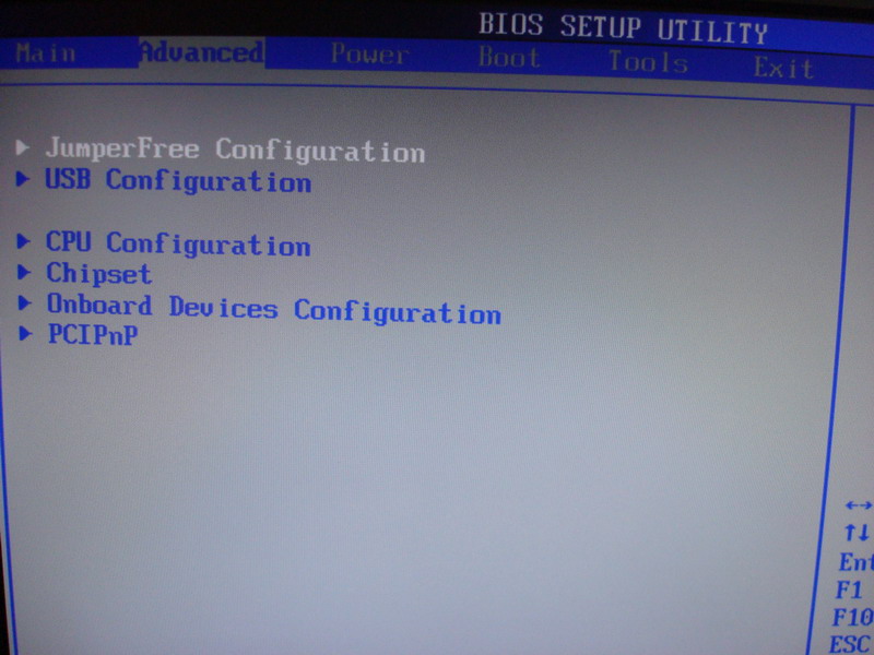
You will see the main page with all your overclocking settings. Some of them will be hidden at first, so you need to change a few things, so that you can see all the options.
Had to split the page into 2 images due to its length.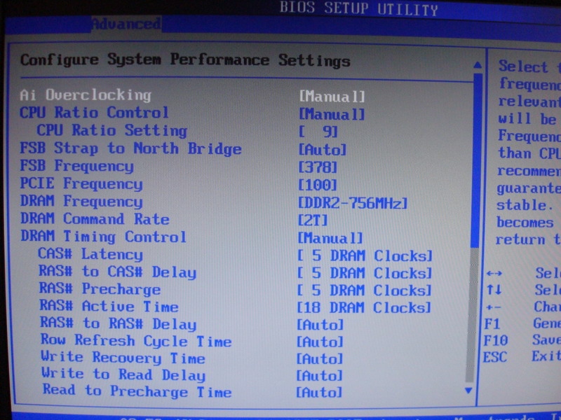

AI Overclocking - Change to MANUAL
CPU RATIO CONTROL – I set this to MANUAL and then CPU RATIO SETTING to 9x for my Q6600. You can leave it on AUTO if you want or change it if you intend using a lower Multi.
FSB STRAP TO North Bridge – I kept it to AUTO (will try to play with it later)
FSB Frequency – Mine stock was 266, and I changed it to 378 to get a CPU Clock of 3.4GHz.
PCI-E Frequency – I always set it to 100. Its bit safer to keep it like that, though, most of the time, people don’t find any issues keeping it to AUTO.
DRAM Frequency – Initially I would suggest keeping it at the lowest divider. 1:1 would be the best option if you are at 333 MHz FSB or higher. If your FSB Frequency is set at 266 at the moment, you would only be able to see 667 setting, use this. You can change it later after finding your best CPU overclock.
DRAM Timing Control – Set this to MANUAL, and you will see all the RAM timings and sub timings. For best stability, enter the first four timings manually exactly matching your ram timings. Usually you can find these written on your ram label. I’ve always found stability issues by keeping those to AUTO, so manually entering it is always better. You can always tighter you timings later if you really want to, off-course after finding your best CPU overclock.
NOTE: Incorrect RAM timings and voltages are one of the most common reason for poor or unstable overclcock, therefore, it is best to enter the correct values manually.
DRAM Static Read Control = AUTO – (Somehow its related to FSB STRAP TO NorthBridge)
Transaction Booster = ENABLED/DISABLED –It helps increasing the overall system performance by a very small margin, if ENABLED. But I set it to DISABLED for ocing. You can keep it ENABLED if you don’t have any stability issues.
Clock Over-Charging Mode = AUTO -- (This option sets the additional voltage supplied to the board clock regulation circuitry. Useful for achieving extreme clocks)
CPU Spread Spectrum = DISABLED
PCIE Spread Spectrum = DISABLED
These Spread Spectrum features are used to reduce the EMI of a given BUS but may compromise your system stability during overclocking. It is best to set the above two DISABLED for best stability.
CPU VOLTAGE = This is where you can add/subtract extra Vcore if needed. (I set it to 1.375 after performing the VDROP and VDROOP MOD to OC my quad at 3.4GHz. You will need to set it according to the type of your processor and the amount of VDROP and VDROOP you have.
CPU Voltage Damper = ENABLED or DISABLED. This is actually meant for eliminating VDROOP and lot of people has found it useful. Didn’t work for me so I set it to DISABLED and did a VDROP and VDROOP MOD for my board (more on this later). You can set it to ENABLED and see if it helps reducing or eliminating the VDROOP, off course if you are experiencing some VDROOP. I found terrible VDROOP on this board. Before doing the MOD mine VDROP was 0.05 and VDROOP was greater than 0.12 (Initially needed to set my Vcore at 1.52 in BIOS for 3.4GHz to get an IDLE Vcore of 1.47 which was dropping to 1.35 under LOAD….resulting in higher core temps. After MOD, BIOS Vcore is set to 1.375, actual is 1.36 and under load is 1.35, temps go only 22C above room temps).
NOTE: Following shots from BIOS HARDWARE MONITOR and CPU-Z showing actual voltages at IDLE and LOAD after VDROP/VDROOP MOD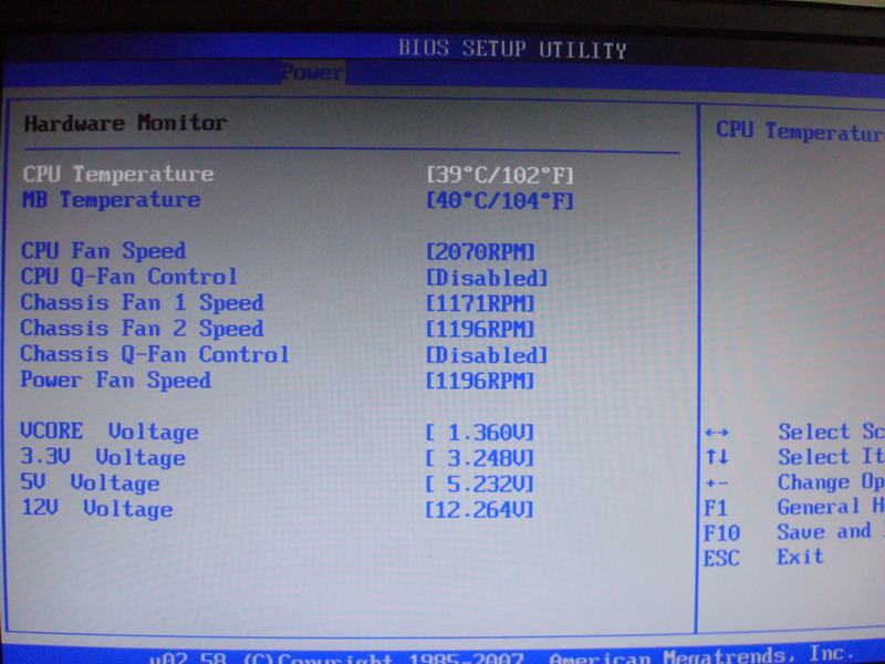
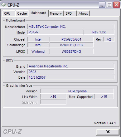
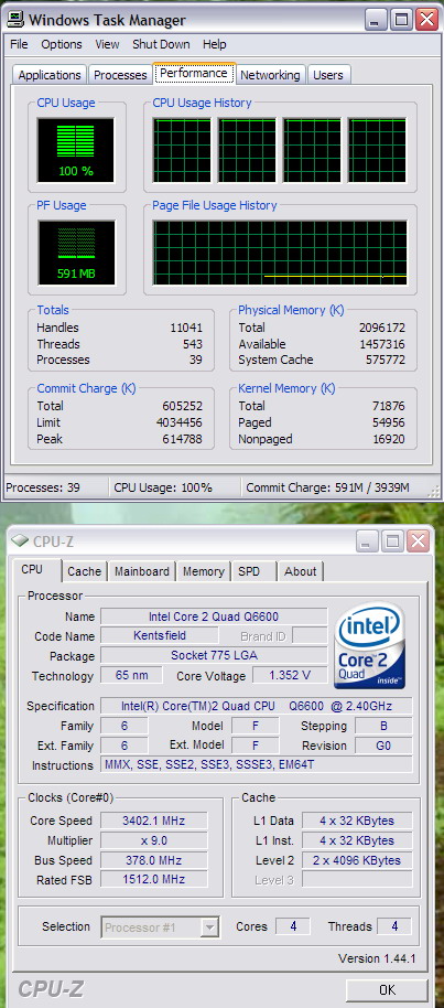
For those who don’t know about VDROP and VDROOP, here is a short explanation.
If you set a Vcore value in BIOS, there is some difference between the voltage shown in the BIOS, and what you actually get (VDROP). And there is also some difference between your idle Vcore and Vcore under load (VDROOP). Amount of VDROOP plays an important role in system stability under load and CPU temperatures.
Click the following link to learn about applying a VDROP/VDROOP PENCIL MOD
VDROP/VDROOP PENCIL MOD FOR ASUS P5K-V
CPU Voltage Reference = AUTO --(Read CPU GTL Reference below)
CPU PLL Voltage = AUTO–(Use to overcome the FSB Wall issue. I won’t suggest playing with it unless you are an extreme tweaker. May damage your hardware)
DRAM Voltage = I would suggest to set this manually. You can find this info on your ram label. I have found AUTO settings quite unstable on most of the systems.
NOTE: Ram is potentially the easiest component when it comes to killing. Overvolting may damage your ram quickly. Kindly consult your ram's label or manufacturer website for correct volatge.
FSB Termination Voltage = Leave at AUTO for now.
North Bridge Voltage = Leave this at AUTO if you are marginally ocing your system, say only couple of 100MHz. Setting this to 1.40 would be more than enough for 1000MHz OC provided that you don’t use lower multipliers and tighter RAM timings. You may need to increase this for very high FSBs and tighter RAM timings AND (may be) if you are using 4 sticks of RAM.
North Bridge Voltage Reference = AUTO--(Read NB GTL Reference below)
UPDATED
BIOS 1001
Ok, Bios updated to 1001. Found the following new settings.
LOAD-LINE Calibration = AUTO/ENABLED/DISABLED—(Previously CPU VOLTAGE Damper. Meant for eliminating VDROOP. I set it to DISABLED)
CPU GTL VOLATGE Reference = AUTO--(Previously CPU VOLTAGE Reference)
NB GTL VOLATGE Reference = AUTO--(Previously NB VOLTAGE Reference)
WHAT IS GTL VOLTAGE REFERENCE?
Gunning Transceiver Logic- Tweaking the GTL Reference voltages for the CPU and Northbridge can sometimes give them better stability. This is particularly noteworthy with (multi core) quad-core processors because, if you’re finding two cores drop off under load, it’s probably down to the fact that the two CPU dies are not identical and while core one and four can hit the FSB you’ve set, the other pair of cores are having trouble. Increasing this level will help bring stability to cpu's at higher FSB's
Memory and CPU suffers from clock miss alignment at higher frequencies. From what I understand, the GTv needs to be adjusted in order to cope with the additional electrical noise created by increased FSBs and electrical current through the motherboard. The GTLv has the ability to 'filter' out noise in the electrical signaling to the CPU and the memory that would cause instability.
Now lets come to the ADVANCED CPU SETTINGS page.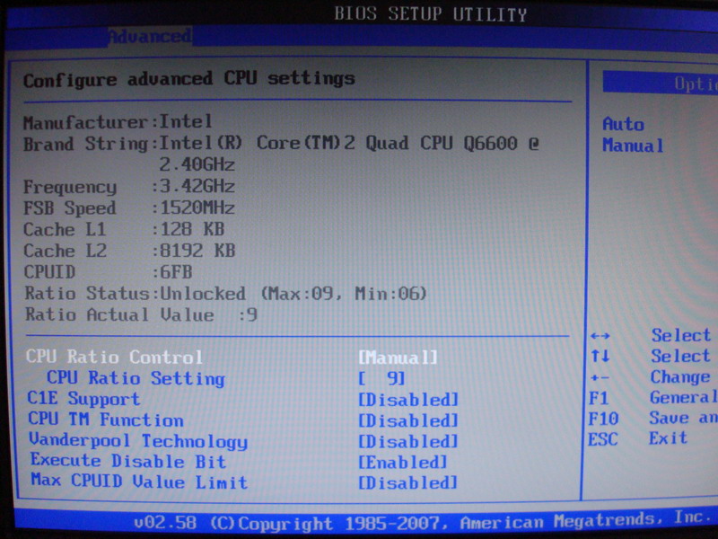
DISABLE everything here except EXECUTE DISABLE BIT (which is used to prevent BUFFER-OVERFLOW). You can DISABLE it if you like.
If you are not doing any bench testing i suggest you should keep the CPU TM Function ENABLED. It affects CPU protection management and help you when you don’t realize you’re pushing your chip too hard. This will keep you safe from damaging your processor.
This concludes our main settings for overclocking on P5K-V. I’ll update this blog as required. I hope it will be useful for some. Kindly leave a comment if you think there is some mistake or you want me to add further related to this.
Thanks!
DISCLAIMER
Overclocking may VOID your components WARRANTY. Overvolting any component carries a high risk of damage and/or failure. I take no responsibility for any loss or damage to your components as a result of using this guide. All overclocking should be done at your own risk.
3 comments:
Very Informative for me ,
Good one keep it up man...........
Glad that you find it useful. Thanks!
i realize i'm a few years late, but i'm running this on one of my systems and doing some upgrades. i wanted to play around with OC'ing and this guide should be a huge help. thank you!
Post a Comment